

Interface
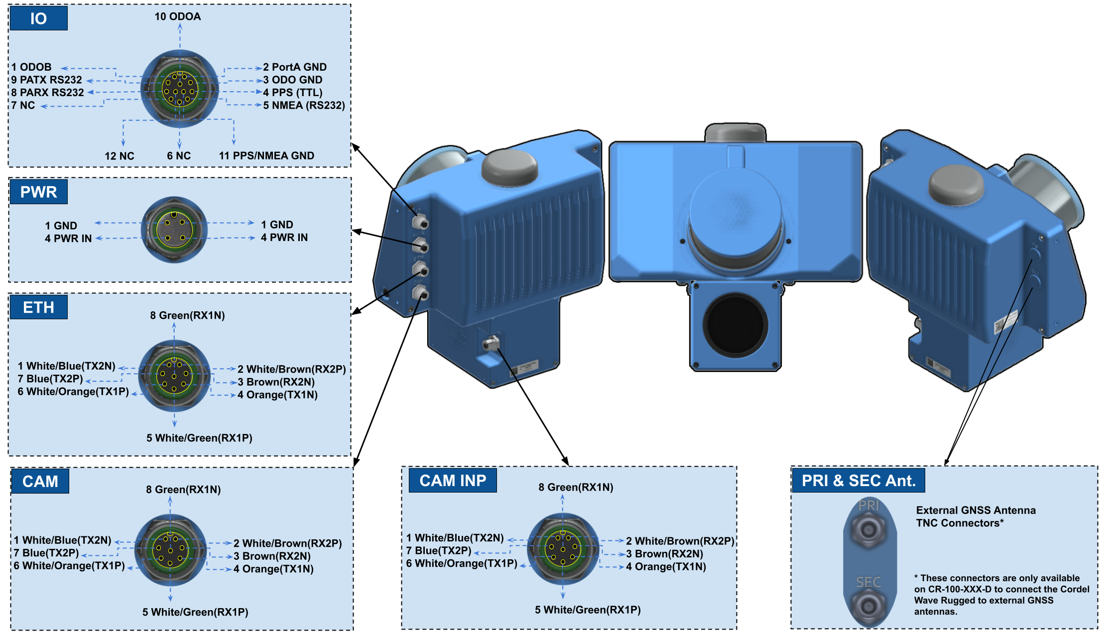
The Cordel Wave-Rugged features M12 A-Coded connectors, as they provide secure and durable connections in environments prone to vibration and/or moisture.
|
Port |
Recommended Connector |
|
|
IO |
PXMBNI12FIM12ASCPGX |
|
|
PWR |
|
|
|
HTR |
||
|
ETH |
PXMBNI12FIM08ASCPGX |
|
|
CAM |
||
|
CAM INP |
||
Note: Standard M12 A-Coded male connectors from other brands are also compatible.
IO pinout
|
Pin No. |
Function |
|
1 |
Odometer B input |
|
2 |
PortA GND* |
|
3 |
Odometer signal GND* |
|
4 |
PPS output (TTL 5V) |
|
5 |
NMEA output (RS232) |
|
6 |
Not connected |
|
7 |
Not connected |
|
8 |
PortA RX |
|
9 |
PortA TX |
|
10 |
Odometer A input |
|
11 |
PPS/NMEA GND* |
|
12 |
Not connected |
* The IO port contains separate electrically isolated IOs to minimise noise injection and avoid ground loops. Where possible, this isolation should be preserved by externally connected devices. We recommend connecting the enclosure to your vehicle ground where possible for the best electrical noise performance.
PWR pinout
The power supply input has an isolated ground to ensure power supply noise does not corrupt communications or cause ground loops with other equipment. The Cordel Wave-Rugged contains an active protection circuit on the power supply input that protects the unit from over/under voltage and reverse polarity.
|
Pin No. |
Function |
|
1 |
GND |
|
2 |
GND |
|
3 |
PWR IN (14VDC to 35VDC) 60W |
|
4 |
PWR IN (14VDC to 35VDC) 60W |
ETH pinout
This port acts as a gateway for communication with the Cordel Wave Rugged through a host machine.
|
Pin No. |
Function |
|
1 |
White/Blue (TX2N) |
|
2 |
White/Brown (RX2P) |
|
3 |
Brown (RX2N) |
|
4 |
Orange (TX1N) |
|
5 |
White/Green (RX1P) |
|
6 |
White/Orange (TX1P) |
|
7 |
Blue (TX2P) |
|
8 |
Green (RX1N) |
CAM pinout (Gen 1)
The Gen 1 Camera connects to the Cordel Wave-Rugged via this interface, which is a PoE Gigabit Mode A Ethernet port.
CAM PORT
|
Pin No. |
Function |
|
1 |
White/Blue (TX2N) |
|
2 |
White/Brown (RX2P) |
|
3 |
Brown (RX2N) |
|
4 |
Orange (TX1N) |
|
5 |
White/Green (RX1P) |
|
6 |
White/Orange (TX1P) |
|
7 |
Blue (TX2P) |
|
8 |
Green (RX1N) |
CAM pinout (Gen 2)
The Gen 2 Camera connects to the Cordel Wave-Rugged via this interface, which is a PoE Gigabit Mode A Ethernet port.
The Gen 2 variant has an additional connector, used to power an in-built heater which prevents condensation forming on the inside of the camera lense.
CAM PORT
|
Pin No. |
Function |
|
1 |
White/Blue (TX2N) |
|
2 |
White/Brown (RX2P) |
|
3 |
Brown (RX2N) |
|
4 |
Orange (TX1N) |
|
5 |
White/Green (RX1P) |
|
6 |
White/Orange (TX1P) |
|
7 |
Blue (TX2P) |
|
8 |
Green (RX1N) |
HTR PORT
|
Pin No. |
Function |
|
1 |
GND |
|
2 |
GND |
|
3 |
PWR IN (14VDC to 35VDC) |
|
4 |
PWR IN (14VDC to 35VDC) |
Electrical Specifications
|
Parameter |
Specification |
|
Operating Voltage |
14VDC to 35VDC |
|
U/O voltage and reverse polarity protection |
Yes |
|
Nominal Operating Voltage |
24VDC |
|
Power Consumption (Typical)* |
60W |
|
GPIO |
5V TTL |
|
RS232 |
|
|
Max Output Current 20mA |
|
|
GNSS Antenna |
Output Voltage 5V |
|
Max Power Consumption 150mA |
Note: If voltages lower than 20V is used, the source should be able to deliver 5A at the switch-on stage, to handle in-rush current. For voltages over 20V, 3A is adequate.
GNSS Embedded Antenna - CR-100-S
The Cordel Wave-Rugged CR-100-S variant is equipped with an embedded GNSS antenna.
GNSS External Antenna - CR-100-D
The Cordel Wave-Rugged CR-100-D variant includes PRI and SEC GNSS antenna inputs, allowing for connection to external antennas that can be placed further away from the sensor. The second antenna allows for better heading alignment, which can slightly improve GNSS post processed results in GNSS denied/degraded environments.
|
Parameter |
Remark |
|
Connector Type |
TNC |
|
Antenna Requirements |
Type: Active, featuring embedded LNA (Low Noise Amplifier) |
|
Gain: 15-50 dB |
|
|
VSWR: < 2.5:1in 1200-1251 MHz and 1560-1610 MHz range |