
This section outlines the installation requirements and recommendations for the Cordel Wave-OEM.
The Cordel Wave-OEM is designed as an integration kit. As such, no strict or generic mounting bracket is provided with the system. This system is designed to be modular allowing for flexibility in installation approaches.
In many applications, Cordel will provide specific mounting instructions and equipment for client applications. Please refer to any specifically supplied documentation for more relevant information.
Always contact Cordel Pty Ltd before installing this kit onto live equipment
Mechanical Specifications
All dimensions are given in mm unless otherwise stated. For more detailed unit or module technical drawings contact Cordel Pty Ltd.
Sensor Head
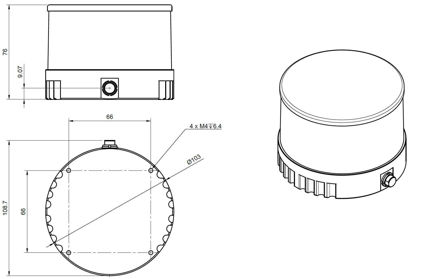
LiDAR
The LiDAR module for the Cordel Wave-OEM is the Hesai PandarXT32. Standard installation involves the use of the M4 bolt holes mounted to the base of the module. For more information refer to the manufacturer’s specifications (Hesai PandarXT).
INS
The INS module for the Cordel Wave-OEM is the Cordel Locate CL-150. Standard installation involves the use of the M3 bolt holes mounted through the provided flange. For more information on this module contact Cordel.
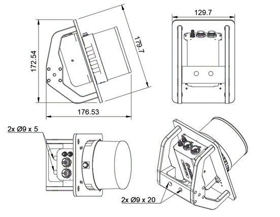
Example Sensor Head Assembly
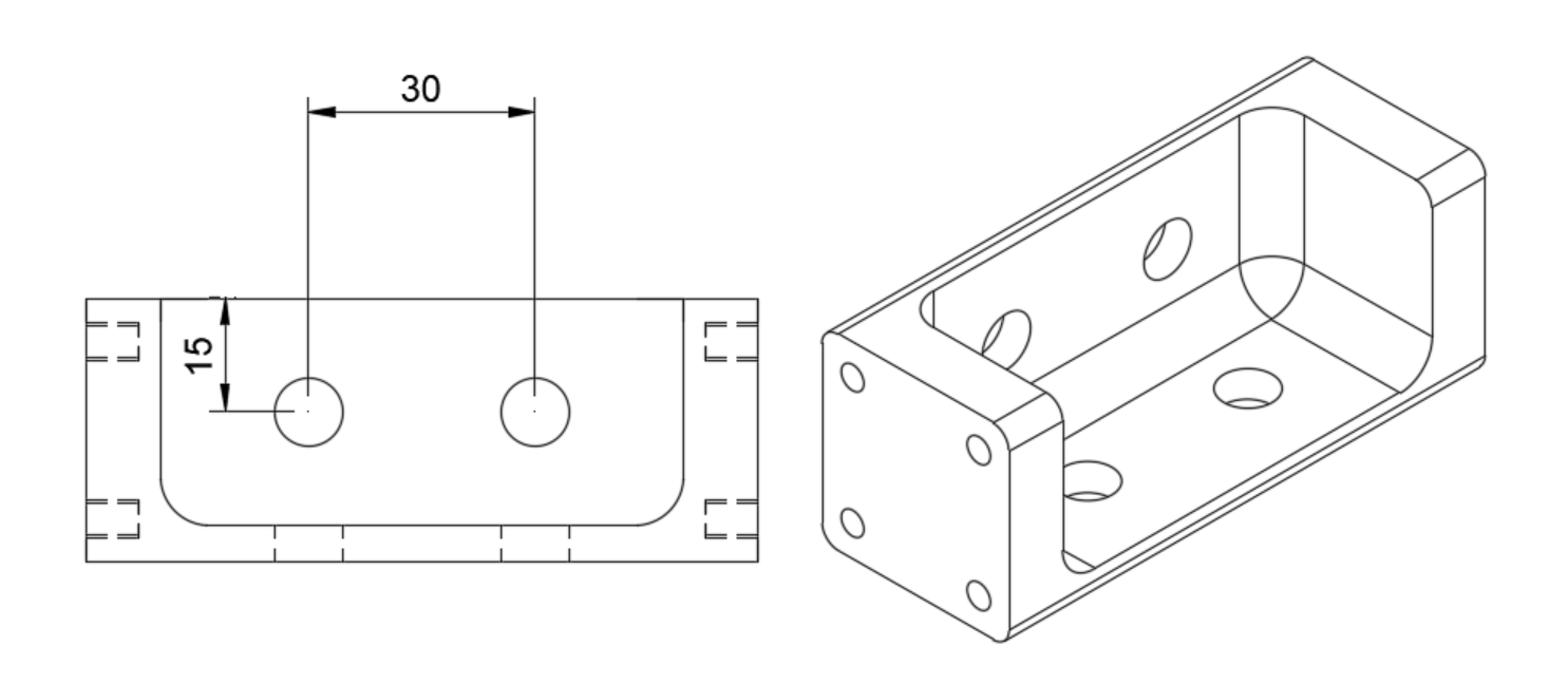
The sensor head consists of the LiDAR and INS module, and these are attached to the LiDAR/INS Mounting head bracket for specific angle control. The angle of the system is angled by 18° to ensure that the bottom channels of the FOV are perpendicular to the ground surface. The M8 passthrough holes are available as mounting positions for custom installations.
Control Unit
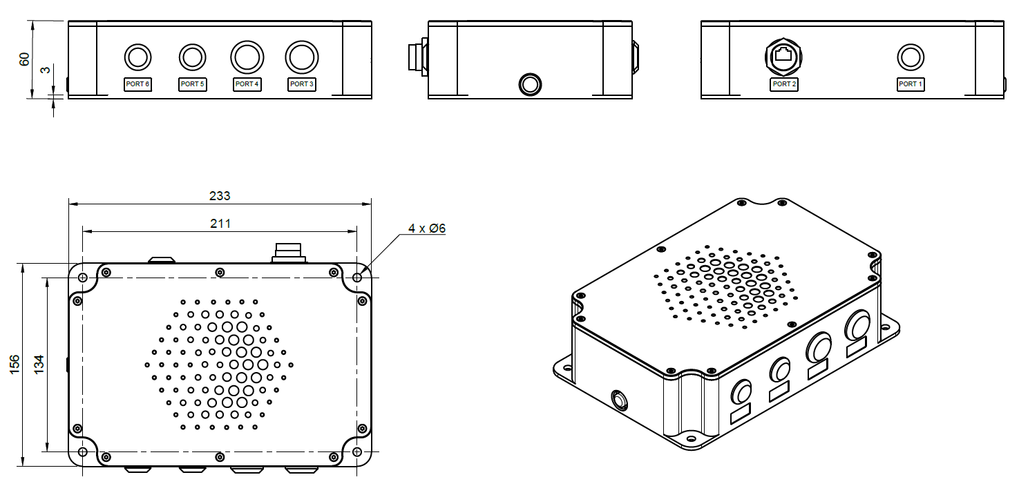
The Cordel Wave-OEM Control Unit contains an IP67 designed enclosure mounted on a 3mm aluminum base, this is designed to be mounted using the flange M5 bolt holes. This module has two revisions, please refer to the module given as the dimensions vary slightly.
Camera
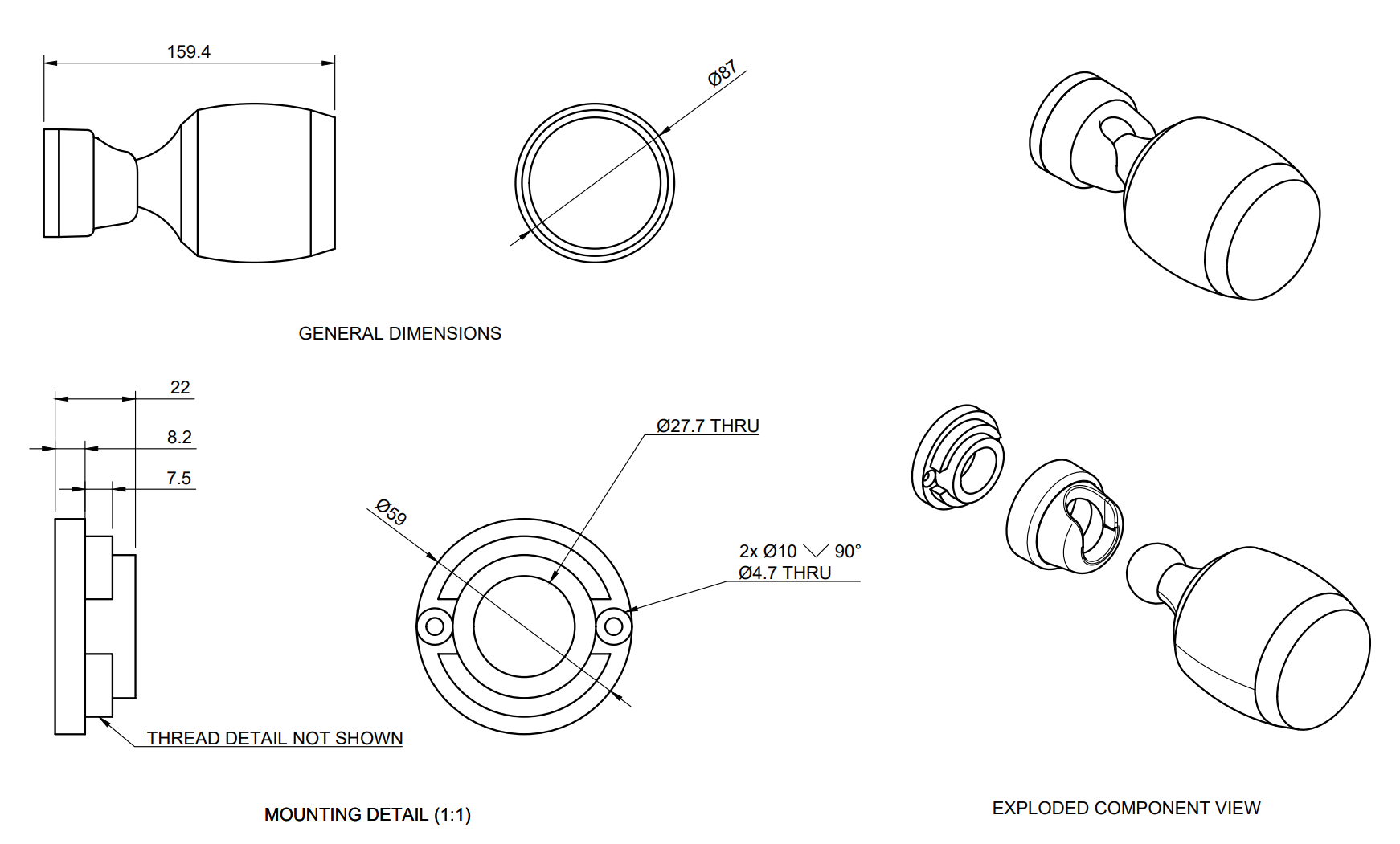
The camera module for the Cordel Evaluation Kit integrates with the Ubiquiti G4 Pro. Standard installation involves the use of the M4 bolt holes provided with the sensor. For more information refer to the manufacturer’s specifications (Ubiquiti G4 Pro).
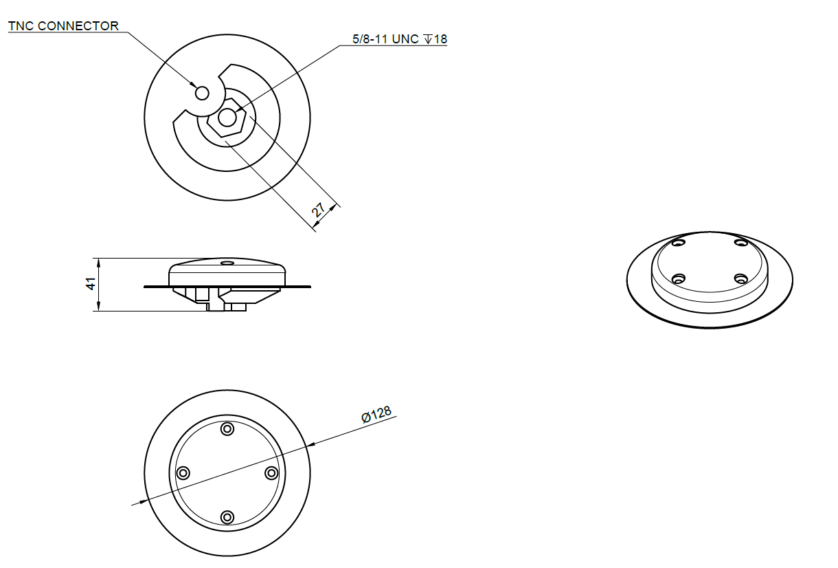
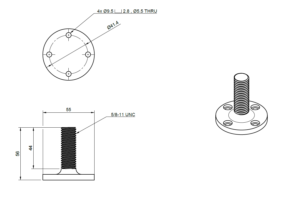
Antenna
The antenna modules for the Cordel Wave-OEM come with the AntCom G5 L1/L2 GNSS. This is provided with a standard 5/8-UNC mounting bracket. This can be attached to the 5/8 UNC stalk and be mounted flush using the M5 bolt holes.