

The Ground Station software has four elements:
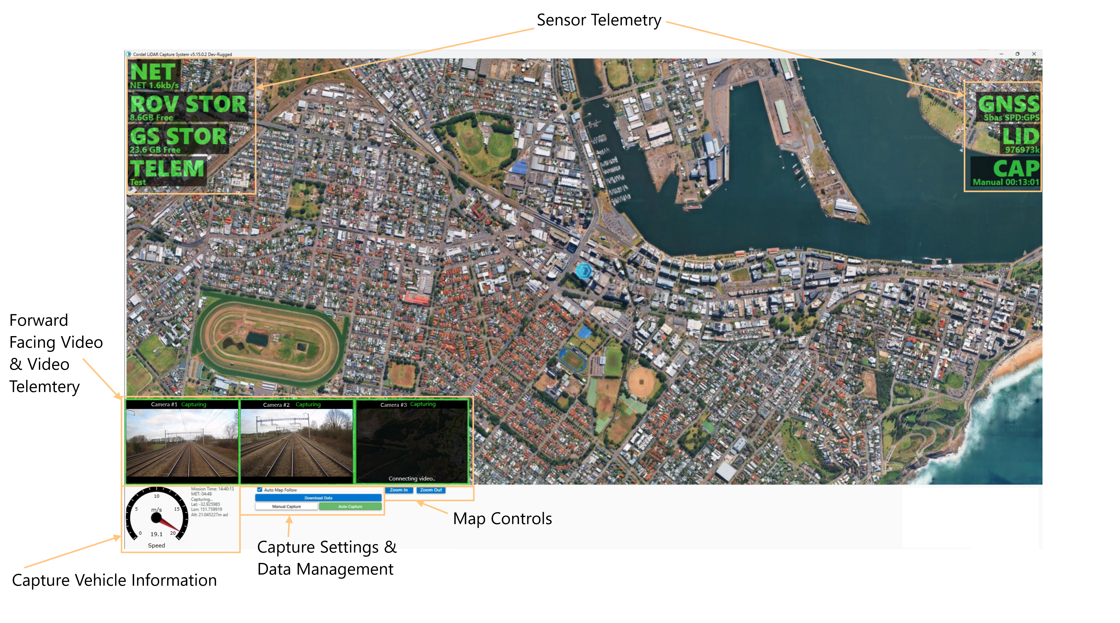
1. Sensor and Component telemetry
Sensor/component labels overlaid onto the map and provide colour-coded information on the status of each component.
General Status Colours
|
Colour |
System Status |
|---|---|
|
Green |
A good indicator that shows the associated component is operating properly. |
|
Yellow |
A warning indicator showing that there may be issues with the associated component or isn’t functioning properly and could cause issues. |
|
Red |
An error indicator showing there is something wrong with the associated component. |
|
Blue |
The associated component is connected and in a ready state, but not actively capturing or recording data at present. |
Sensors and Components
GNSS Status (GNSS) Sensor
|
Colour |
System Status |
Sub Information Displayed |
|---|---|---|
|
Green |
Good GNSS Fix |
“Fix Type”
|
|
Yellow |
Warning in the GNSS Fix |
“Warning Message”
|
|
Red |
Error in submodule |
“Error Message”
|
|
Blue |
N/A |
N/A |
LiDAR Status (LID) Sensor
|
Colour |
System Status |
Sub Information Displayed |
|---|---|---|
|
Green |
Capturing |
“Total Points Collected” |
|
Yellow |
N/A |
“Warning Message”
|
|
Red |
Error in submodule |
“Error Message”
|
|
Blue |
Ready to capture |
Ready Waiting… |
Capture Status (CAP) Component
|
Colour |
System Status |
Sub Information Displayed |
|---|---|---|
|
Green |
Capturing |
CAP “Elapsed Time” |
|
Yellow |
Warning in submodule |
N/A |
|
Red |
Error in submodule |
N/A |
|
Blue |
Ready to capture |
READY “Capture Mode”
|
Network Status (NET) Component
|
Colour |
System State |
Sub Information Displayed |
|---|---|---|
|
Green |
Network Present and data decoding |
WIFI “Connection Speed” |
|
Yellow |
N/A |
N/A |
|
Red |
Network present but unable to decode system data |
NO RADIO |
|
Blue |
No Network Connected |
NO NET |
Rover Storage Status (ROV STOR) Component
|
Colour |
System Status |
Sub Information Displayed |
|---|---|---|
|
Green |
More than 10 GB of storage |
“Storage Size Available” |
|
Yellow |
Between 5GB and 10GB of storage |
“Storage Size Available” |
|
Red |
Less than 5GB of storage |
“Storage Size Available” |
|
Blue |
N/A |
N/A |
Ground Station Storage Status (GS STOR) Component
|
Colour |
System Status |
Sub Information Displayed |
|---|---|---|
|
Green |
More than 10 GB of storage |
“Storage Size Available” |
|
Yellow |
Between 5GB and 10GB of storage |
“Storage Size Available” |
|
Red |
Less than 5GB of storage |
“Storage Size Available” |
|
Blue |
N/A |
N/A |
2. Forward Facing Video Stream & Video Telemetry
A live video feed from each camera is displayed in the bottom left corner of the Ground Station software, including live camera telemetry information.
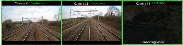
The table below describes what information is displayed, where:
|
Information |
Location |
Example |
Notes |
|---|---|---|---|
|
Camera Name |
Top Left |
Primary |
This is configured on the hardware device and does not change during capture. |
|
Hardware Status |
Top Right |
Capturing |
|
|
Camera Recording status |
Border Colour |
Green |
Colour coded |
|
Hardware / Ground Station Connection Status |
Bottom |
Connecting video.. |
the camera video stream status is not shown once connected, unless there are errors. |
Hardware and Camera Recording Status
The table below shows potential combinations of Hardware Status and Camera Recording Statuses, as well as which combinations are expected, and which may require troubleshooting:
|
Hardware Status |
Camera Recording Status |
Vehicle capturing? |
Camera recording? |
Meaning |
|---|---|---|---|---|
|
Capturing |
Green |
Yes |
Yes |
The hardware unit is capturing, and the camera is recording (expected). |
|
Capturing |
Red |
Yes |
No |
The hardware unit is capturing, but the camera is not recording; needs attention. |
|
Connected |
Green |
No |
No |
The hardware unit is not capturing, and the camera is connected but not recording (expected). |
|
Connection |
Red |
Either |
No |
The hardware unit is unable to connect to the camera. |
|
Init |
Red |
Either |
No |
The camera failed to start. |
|
Status |
Red |
Either |
Not known |
The hardware unit is unable to read the status of the camera. |
|
Unknown |
Blue |
Not known |
Not known |
No recent update from the hardware unit. |
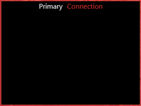
Hardware and Ground Station Connection Status
The table below provides a list of the possible Connection Statuses, as well as which statuses are expected, and which may require troubleshooting:
|
Text |
Colour |
When |
|---|---|---|
|
Connecting video.. |
White |
When the feed first opens, before any picture arrives. |
|
(nothing) |
— |
The video is showing. The message is hidden once connected. |
|
Reconnecting video.. |
White |
The stream dropped or errored. It retries every 3 seconds and clears once the picture returns. |
|
High quality video |
Red |
Shown permanently, below the line above. This appears when the camera has no low-quality stream set up, so the Ground Station uses the full-quality stream instead. This can be slow or laggy over the radio link. |
3. Capture Vehicle Information
The capture vehicle information is located on the left side of the display. This area includes:
Capture vehicle speed: Displays the speed of the capture vehicle in M/S (metres/second) using a speedometer-style display
-
Mission time: the current time - set by the time on the Ground Station Host Machine.
-
MET: Mission Elapsed Time - the amount of time elapsed during the current capture.
-
Status:
-
“Capturing…” the system is actively capturing data
-
-
Location: The current position (latitude, longitude and altitude) of the capture vehicle.
3. Capture Settings & Data Management
The capture settings & data management area allows users to set the capture mode to manual or automatic, as well as toggle the “auto map follow” option on and off.
-
Automatic Capture: data capture is based on vehicle movement being detected.
-
Manual Capture: data capture is started and stopped manually by the user, using the corresponding buttons.
-
Auto map follow: displays the Ground Station icon on the map and syncs the icon’s movement to the capture vehicle’s movement.
4. Map Controls
These buttons allow user to zoom in and out of the map.
USB Copy Enabled
This checkbox allows automatic transfer of capture data to an external drive. See how to transfer data to an external drive automatically for more information on how to enable and utilise this function.
Related Articles
-
(V4.0) How Transfer Data From Cordel Capture Hardware To The Host Machine
-
(V4.0) How To Transfer Data From The Host Machine To Cordel Connect
-
How to monitor the health of capture hardware in Cordel Connect